

Got a Question? Contact me at enquiries@virtualfrontiers.co.uk
Putting Your I/O Board Together
So now we (hopefully) have a working LCD and IR receiver sitting on a breadboard. wouldn’t it be better to mount all this on a separate board? This process took me most of a day because I am very clumsy with a soldering iron and every time I soldered a joint I stopped to test each join to make sure I hadn't accidentally bridged a connection (Which I did several times). Hopefully you will be better at this than I am, this was my first ever attempt at building my own board.What You Need
1. A soldering iron and solder 2. A stripboard (Pick one up at your local Maplins) 3. A Spot face cutter for the stripboard 4. An IR Module 5. An LCD Module 6. A PNP type transistor 7. Some Jumper wire 8. A heatsink clamp (For the transistor IMPORTANT!) 9. A multimeter (optional -but very handy) 10. A desoldering pump or braid (For when you accidentally solder a wire to the wrong strip.)Design your Board Layour
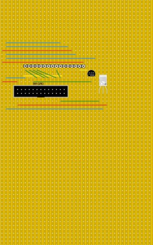
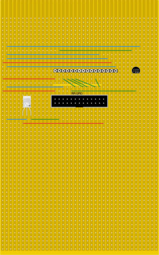
I would not recommend trying to wire up your board without laying out a design in advance. you can either do it on paper or get some stripboard design software. I used Lochmaster to do my layout and it’s fairly simple to use. You can get a demo version of it to try out. here are the layouts I designed. the one on the left is for the DEM LCD board, the one on the right for a standard HD44780 which has a slightly different pin layout than the DEM. You’ll notice above that I have designed this with the Raspberry Pi A/B’s 26 pin connector. If you are using a Pi A+/B+ or above then you can either replace the 26 pin connector with a 40 pin connector, the pins we are using are in the same location, or get a 40pin to 60 pin cable. It's also not visible on the board layout, but you will have to break the tracks between the row of pins on the Pi Connector. The Spot Face cutter can’t do this as it breaks connections on the pin holes. I used a dremel to carefully cut the connections but a scalpel or craft knife should be able to do the job just as well. Also note that in these layouts, I have just put pin sockets where the LCD board will plug in. In actuality I soldered the LCD directly to the board but I wouldn’t recommend it. easier to get some pin sockets so that you can unplug the LCD board easily. Also if, like me, you're new to soldering components, it is important to clip a heatsink clamp to each leg of the transistor as you solder it. Transistors are easily damaged by heat. As I found out three burned out transistors later. Once you are done you can (Very carefully) trim of the unused parts of the board with a junior hacksaw be careful doing this, however, as you may break some solder joints. (Yep, I did that too)The Finished Product
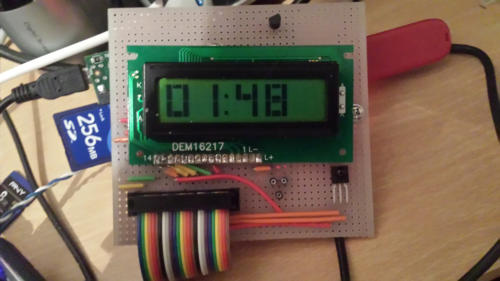
Once you’re done you should (hopefully) be left with something like this: You’ll probably note that the transistor is not in the position specified in my layout. this is due to my repeated cockups trying to solder the transistors to the board before I discovered the importance of a heatsink clamp.